
For HVAC professionals
Install the GraviTrip™ in seven steps.
Step-by-step instructions based on the factory installation insert and the installation video. Read the whole guide before you start, then work through each step and finish with the functional test.
Watch first
Installation video
See every step in about two and a half minutes, then follow the written guide as you work. The chapters match the steps below.
The installation video is coming soon. Until then, follow the written steps below.
Chapters
- Before you begin
- 1. Shut off power
- 2. Assemble the bottle
- 3. Choose placement and mount the switch box
- 4. Set the chain and clip
- 5. Connect the drain and adaptor
- 6. Wire the low-voltage switch
- 7. Finish, test the trip weight, and reset
- After a water shutdown and maintenance
- Installation complete
Read before installing
Safety first
Danger / warning: risk of electric shock
- Disconnect or shut off power to the HVAC equipment before installation or service.
- Installation by a qualified HVAC technician or licensed electrician only.
- For low-voltage HVAC control circuits only. Do not connect to 120/240 VAC line voltage.
- This device is a supplemental safety device. It is not a leak detector.
-
Qualified installers
An HVAC technician or licensed electrician must install the kit.
-
24 VAC controls only
Low-voltage control circuits only. Never connect to 120/240 VAC.
-
Indoor use only
Keep the switch box dry and protected from weather.
Follow the HVAC equipment manufacturer's wiring diagram, and confirm the installation meets local code and the equipment manufacturer's requirements before wiring.
Before you begin
Check the kit, tools and site
This kit helps reduce the risk of condensate overflow by tripping a switch when water routed to the collection bottle reaches the set fill level. Where the equipment manufacturer permits it, you can wire the switch to interrupt the HVAC low-voltage control circuit.
Kit contents: verify before installation
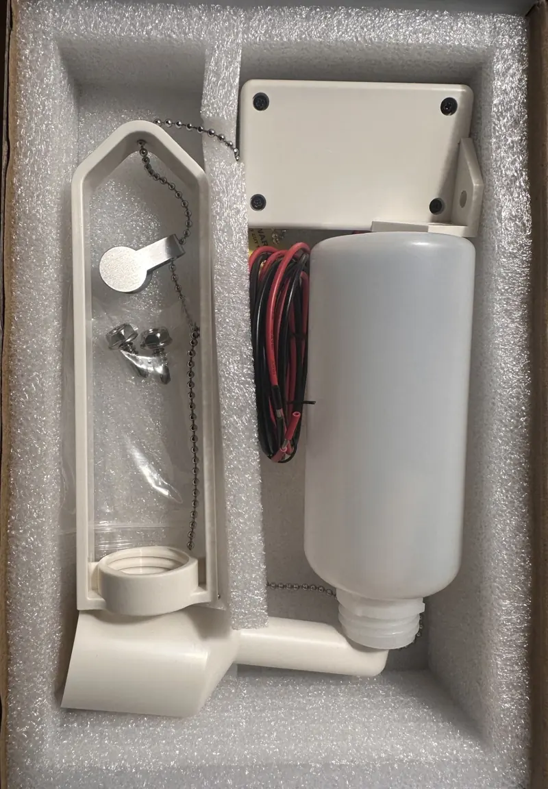
- Switch box assembly: UL 61058-rated switch in a UL 94 V-1-rated switch box, with wiring leads
- Bottle hanger
- Collection bottle
- L-type adaptor: antimicrobial, to reduce algae buildup
- Chain assembly: full factory length, part of the calibrated trip weight
- Chain clip
- Mounting screws (2)
- Red and black wire leads: one pair, 18 AWG, UL 1007-rated
Also in the box: the instruction and warning insert. Inspect every part, and do not install cracked, bent, corroded, missing or damaged components.
Tools & materials (not included)
- Voltage tester, to verify power is off
- Screwdriver or drill/driver for the mounting screws
- 3/4-inch PVC pipe and fittings, PVC cutter or saw
- Approved PVC cement (and primer, where local code requires it)
- Wire nuts or approved low-voltage connectors
- Wire cutter/stripper
- Wire ties or clips to secure low-voltage wiring
- Water for the functional test
Choose a location that…
- Lets condensate overflow run downhill through PVC to the bottle
- Stays accessible for inspection and emptying
- Is clear of walkways, moving parts, heat sources and sharp edges
- Has a stable support for the switch box that can hold at least 2.2 lb, including water load, vibration and service handling
- Lets the switch box sit directly above the bottle
- Is indoors, dry and out of reach of children
What you're building
Installation overview
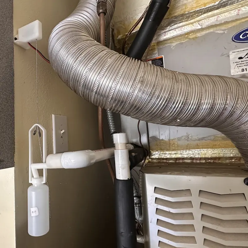
The switch box mounts above the collection bottle. The full chain hangs straight down to the bottle hanger, and overflow from the condensate drain runs downhill through 3/4-inch PVC into the bottle.
- Installer
- HVAC technician or licensed electrician
- Control circuit
- Indoor 24 VAC, in series on R
- Drain route
- 3/4-inch PVC, continuous downward slope
- Switch box support
- Holds at least 2.2 lb
- Weight-activated switch box, mounted above the bottle
- Switch leads to the 24 VAC control circuit
- Calibrated chain, full length, hanging straight down
- Bottle hanger, with the chain clip at the top
- L-type adaptor, bonded to the PVC with its narrow end in the bottle
- Collection bottle
- Condensate drain connection
- Air handler
Installs in three stages
Start by shutting off power in step 1, then work through each stage.
Step 1 of 7Shut off power
- Turn off power to the HVAC equipment at the service disconnect, breaker or main electrical panel.
- Verify that power is off before you open any HVAC panel or make electrical connections.
- Keep power off until all wiring is complete.
Power stays off until step 7.
Restore power only after the low-voltage wiring is secured and every cover is back on.
Step 2 of 7Assemble the bottle
- Thread the collection bottle A into the bottom of the bottle hanger B.
- Turn it until it's secure.
- Keep the bottle A upright.
Seat the bottle fully. Bottle seating is one of the first things to check if the functional test fails.
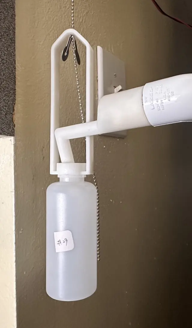
- Collection bottle: keep it upright
- Threaded connection: the bottle screws into the base of the hanger
Step 3 of 7Choose placement & mount the switch box
3.1 Plan the placement
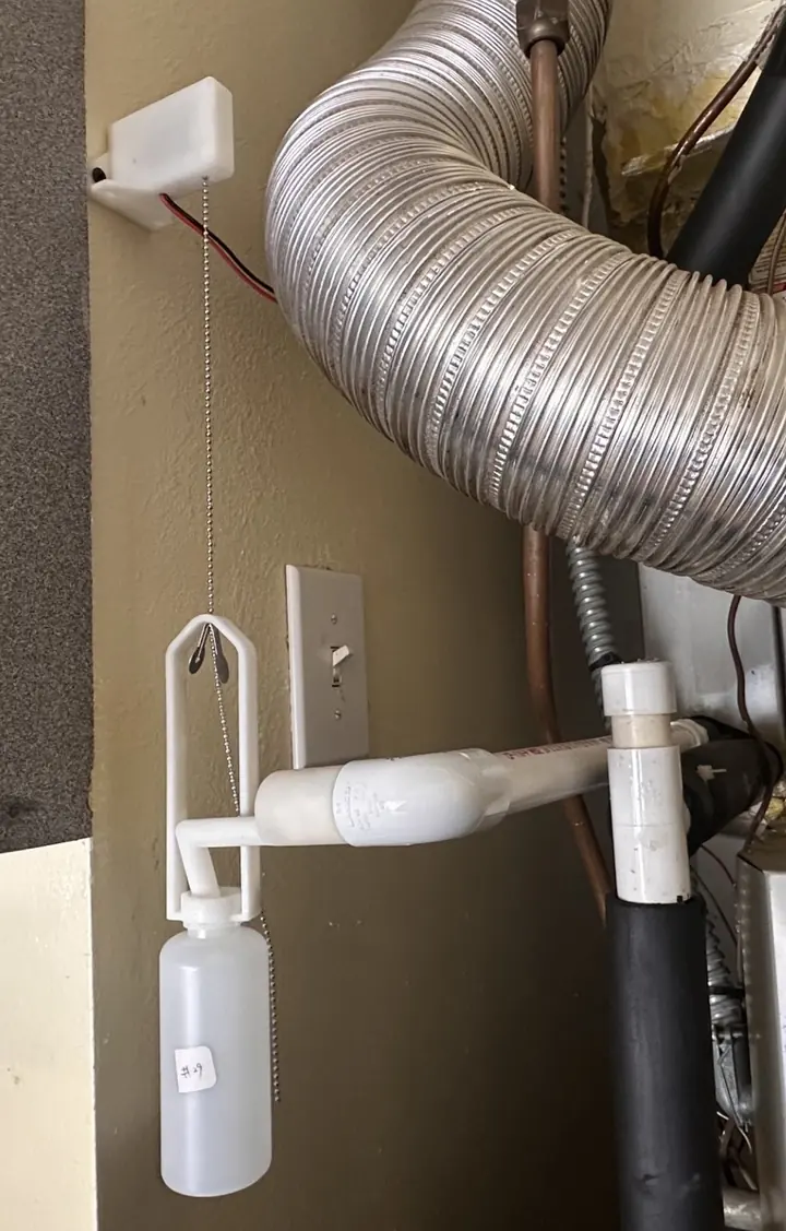
- Collection bottle, where overflow collects
- Condensate drain connection
- PVC route, running downhill to the bottle
- Switch box, directly above the bottle
- Chain, hanging straight down
3.2 Mount the switch box
- Fasten the switch box A to a stable support that can hold at least 2.2 lb, using the two supplied mounting screws B.
- Let the chain C hang straight down to the bottle hanger.
- Keep the box A dry, and keep the hanging assembly clear of other components.
The bottle must hang vertically and move freely.
It must not rub, bind or touch other components.
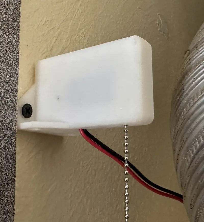
- Switch box, kept dry
- Mounting screw into a stable support
- Chain to the bottle hanger
- Low-voltage leads (red and black)
Step 4 of 7Set the chain & clip
Calibration warning: keep the full chain
The control switch is factory calibrated to activate at a specified suspended load, and the full factory-supplied chain is part of that load. Do not cut, shorten, remove links from, replace or otherwise alter the chain. Keep every link attached and fully suspended, and don't let excess chain rest on another surface.
- Thread the chain through the hole A at the top of the bottle hanger.
- Slide the chain clip B along the chain to set the distance between the switch box and the bottle hanger, so the L-adaptor will sit properly inside the bottle.
- When the distance is right, squeeze the ends of the clip B together to secure it.
- Adjust the clip B, never the chain length. Do not cut off any excess chain.
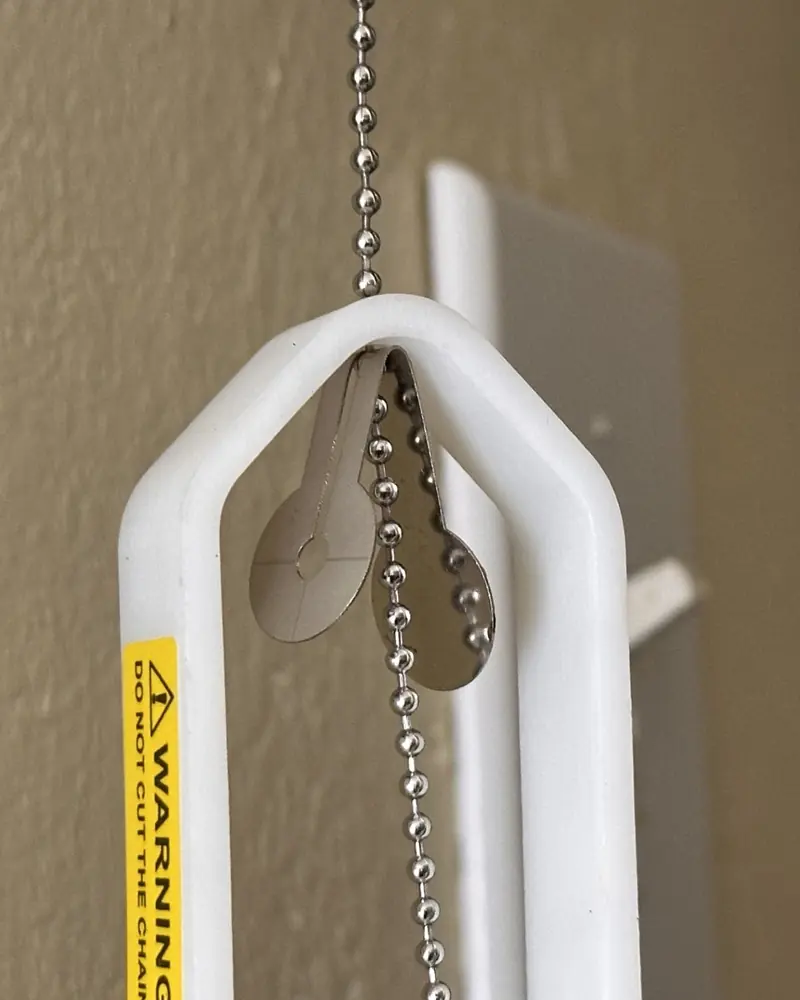
- Top hole: the chain threads through here
- Chain clip: slide to adjust, then squeeze the ends closed
- Warning label: do not cut the chain
Step 5 of 7Connect the drain & adaptor
5.1 Slope the drain pipe
- Route condensate overflow from the drain connection A to the collection bottle with 3/4-inch PVC B.
- Give the pipe B a slight, continuous downward slope toward the bottle so water flows freely.
- Keep the water path clear. Do not kink, crush or obstruct the piping B.
Water must flow freely toward the bottle.
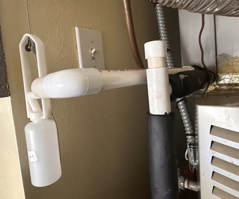
- Condensate drain connection
- 3/4-inch PVC, sloping toward the bottle
- L-adaptor, bonded to the PVC
- Narrow end, down inside the bottle
5.2 Bond the L-adaptor and check alignment
- Bond the L-type adaptor A to the PVC B with approved PVC cement C.
- Place the adaptor's narrow end D down inside the bottle.
- Check the alignment. The bottle should hang vertically, and the piping and adaptor A must not restrict, rub or bind the hanging assembly.
- If needed, reposition the chain clip (step 4) to get the alignment right.
Keep the bottle and hanger free to move.
The adaptor must not restrict the hanging assembly, or the switch may not trip.
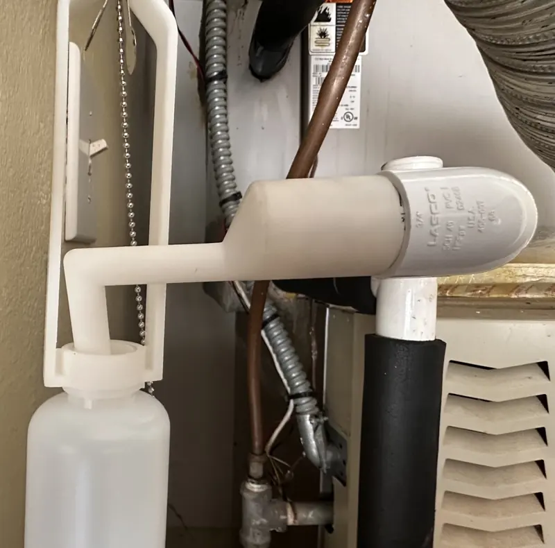
- L-type adaptor
- 3/4-inch PVC elbow
- PVC cement at this joint
- Narrow end inside the bottle
Step 6 of 7Wire the low-voltage switch
Power must still be off.
Before doing any wiring, confirm power to the HVAC system is off at the breaker or main electrical panel.
- Locate the low-voltage thermostat cable where it enters the air handler or furnace control area.
- Identify the 24 VAC R (red) control wire, using the HVAC equipment wiring diagram.
- Cut the R control lead.
- Connect one AC Flood Guard switch lead to each cut end with wire nuts or approved low-voltage connectors. This puts the switch in series on R.
- Leave the other control wires as they are. Do not connect the switch across R and C.
All wiring is low voltage (24 VAC).
Use appropriate low-voltage materials and keep wires away from line-voltage components. If the equipment manufacturer calls for a different control or alarm circuit, follow its requirements.
Step 7 of 7Finish, test the trip weight & reset
7.1 Secure, cover and power on
- Secure the low-voltage wires and keep them away from line-voltage components.
- Reinstall all covers.
- Restore power to the HVAC system.
7.2 Test the trip weight
- Add water to the bottle A until the switch activates.
- Confirm the HVAC system shuts down, or that the selected alarm or control circuit activates.
When the bottle reaches the trip weight, the weight of the water trips the switch.
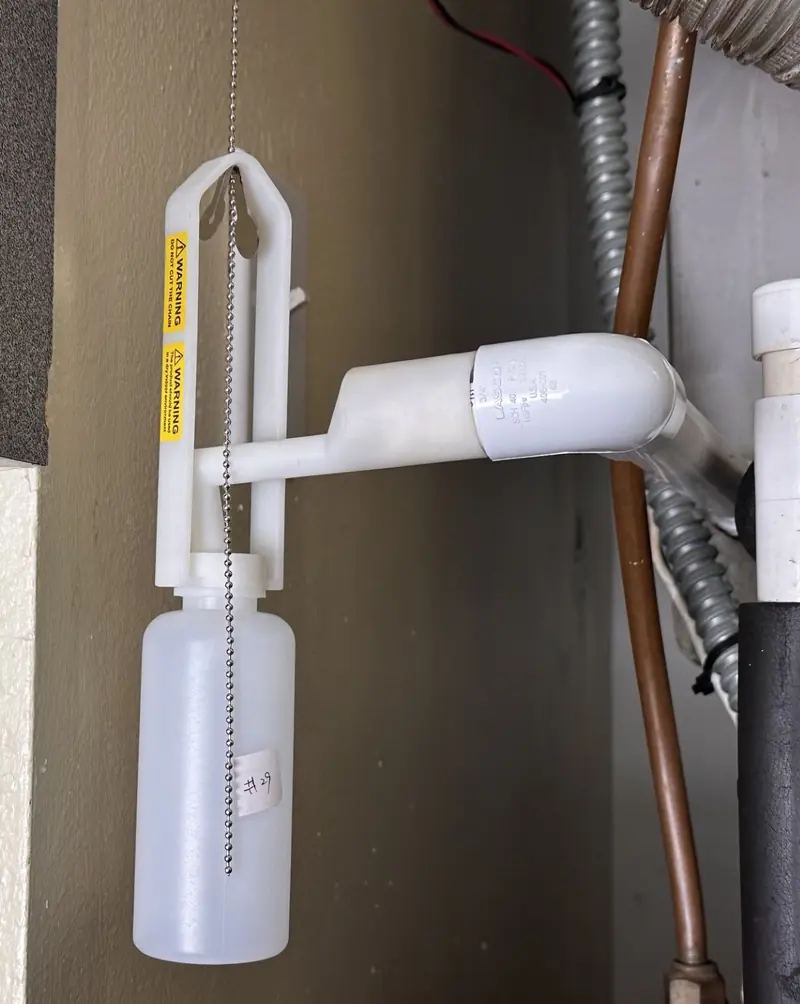
- Add water to the bottle to test the trip weight
- Gently pull the chain to reset the switch
7.3 Empty, refit and reset
- Empty the bottle A and refit it securely.
- Gently pull the chain B to reset the switch.
- Confirm that normal operation returns.
Emptying the bottle alone does not reset the switch.
Always finish by gently pulling the chain.
7.4 If the test fails
Power off
Disconnect power before making changes.
Check
Mounting, chain routing or clip position, bottle seating, adaptor alignment and wiring.
Retest
Correct the issue, then test the shutoff again.
Do not use the unit until the test passes.
Installation complete. Before you leave, show the homeowner how to reset.
Empty the bottle, refit it, then gently pull the chain. Point them to what to do after a shutdown.
After installation
After a shutdown & ongoing maintenance
After a water shutdown: clear the cause first
- If the HVAC system shuts off and the bottle contains water, treat it as a drain or overflow condition.
- Have a qualified technician inspect and clear the condensate drain problem.
- Empty and refit the bottle, then gently pull the chain to reset the switch.
- Correct the overflow problem before restarting.
Ongoing maintenance: keep the system ready
- Test the switch and inspect the entire installation every six months.
- Inspect the bottle, hanger, chain, clip, adaptor, screws and wiring after any HVAC service.
- Keep the bottle upright and clean. Clean it with mild soap and water only.
- Replace the complete unit if any component is damaged, discolored, cracked, corroded, loose or unreliable.
Know the limits
Use restrictions & important limitations
Use restrictions
- Indoor use only.
- For low-voltage 24 VAC HVAC control circuits only. Do not use above the approved control voltage.
- Do not submerge the switch box or expose it to outdoor weather.
- Do not install in corrosive or explosive atmospheres, or where children can reach the kit.
- Dispose of electrical and electronic components according to local e-waste rules.
Important limitations
- This is a supplemental safety device, not a leak detector.
- It does not detect leaks outside the collection path, internal evaporator-pan overflows that aren't routed to the bottle, freezing, power loss, or improper installation.
- Activation may come early, late or not at all if the chain is cut, shortened, has links removed, is replaced or is otherwise altered. The switch is calibrated for the weight of the complete factory-supplied chain.
Sign-off
Installer checklist
Run through this list before you leave the job. Your checks are saved in this browser tab only.
Resources
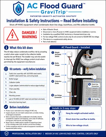
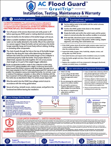
Installation, testing, maintenance & warranty insert
The two-page insert that ships in every kit, including the full warranty.
Download PDF (1.3 MB)Questions on a job?
Send us your question through our contact form, and we'll get back to you.